Installation Instruction (Step by Step)
The rain sensor is rugged, reliable, low maintenance and easy to install. The sensor has a relay switch contact (dry contact) which can be connected to your external system or controller using a cable.
The following sections is a step by step handy installation guide to setup your rain sensor.
Tools & Accessories for Installation
- RG-11 Rain Sensor
- Phillips screwdriver
- Flat-head screwdriver or test-pen
- Cable/wire stripper
- Wire cutter
- Cable (3 to 5 core cable 22AWG), jacket diameter Ø4-6mm
- Mounting bar/platform for Rain Sensor
- 2x M6 hex screws/washer/nut, and spanner tools
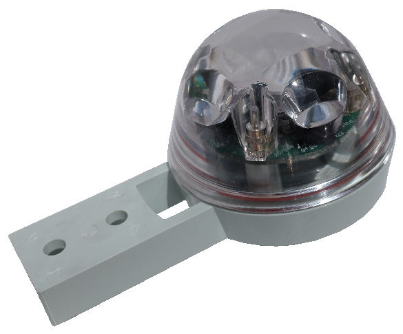
Open Up the Rain Sensor
The rain sensor is fully assembled from the factory when you first unpack it from the package box. You will need to open up the rain sensor for the wire connections and also to configure its operating mode.
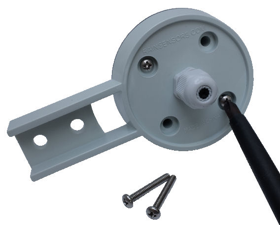
There are 4x pieces of cross head screws below the base of the sensor as illustrated in the photo. Use a Phillips screwdriver to unscrew out all the 4 screws.
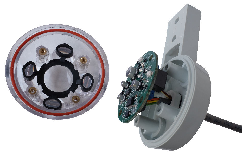
List of Rain Sensor Parts
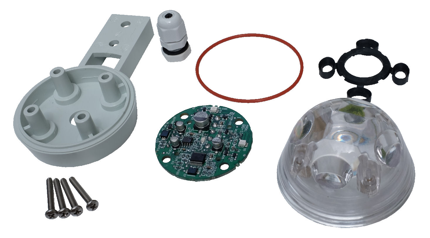
These will be the individual parts that you will get to see after you have dismantled the rain sensor. Be careful when handling the parts. Do not lose them.
You may also find a “Silica gel pack” inside the casing. It is not part of the rain sensor. You can throw away this pack.
With reference from the photo, the rain sensor parts are listed in clockwise order starting from the 4 screws (lower left).
Rain Sensor Parts List
- 4x stainless steel screw, round cross head #6-32 x 1 inch (⌀ 0.138inches or 3.51mm)
- Rain Sensor base mount
- Cable gland set
- Rubber gasket (red colour), silicone o-ring size-036
- IR light guide (black colour)
- Optical dome cover (transparent)
- Rain Sensor circuit board (green colour)
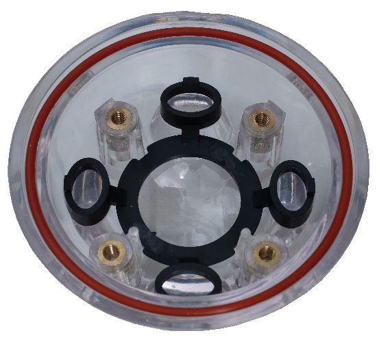
Please ensure that the red coloured gasket rubber band is inserted properly on the edge of the optical dome cover. This rubber gasket prevents the rain water from seeping in.
There is also a black coloured plastic light guard. This is there to guide the IR light into the optical dome cover to minimise stray light.
Cable Gland Fitting
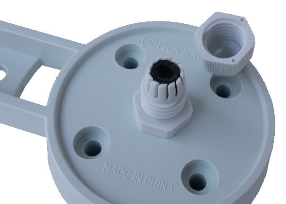
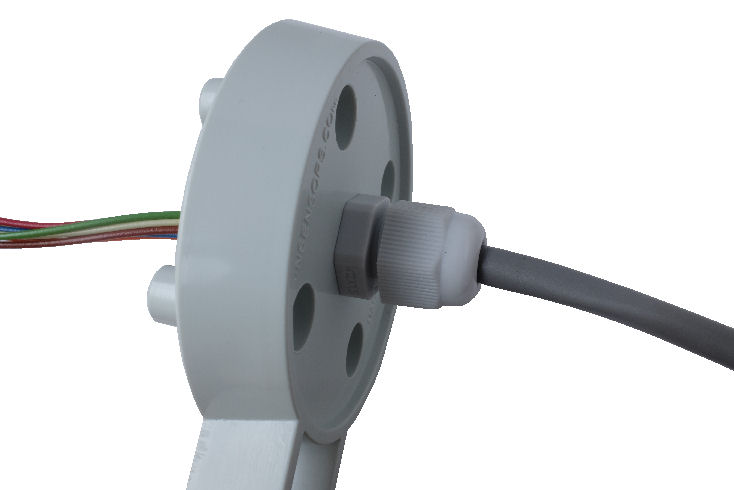
At the bottom of the sensor, you will see a cable gland. This is where the cable connecting to the rain sensor circuit will be coming out from.
The cable gland is suitable for cable’s jacket diameter range from Ø4mm to Ø6mm. If the cable diameter is too small, the cable gland may not be able to apply sufficient pressure for water tight. If it is too big, it is difficult to pull the cable through the cable gland.
Unscrew the cable gland’s cap to prepare for the cable insert. Please take note of the black rubber gasket inside the cable gland. This rubber gasket ensures that the cable entry outlet is sealed tight from the rain water outside.
Cable Selection, Strip to Length
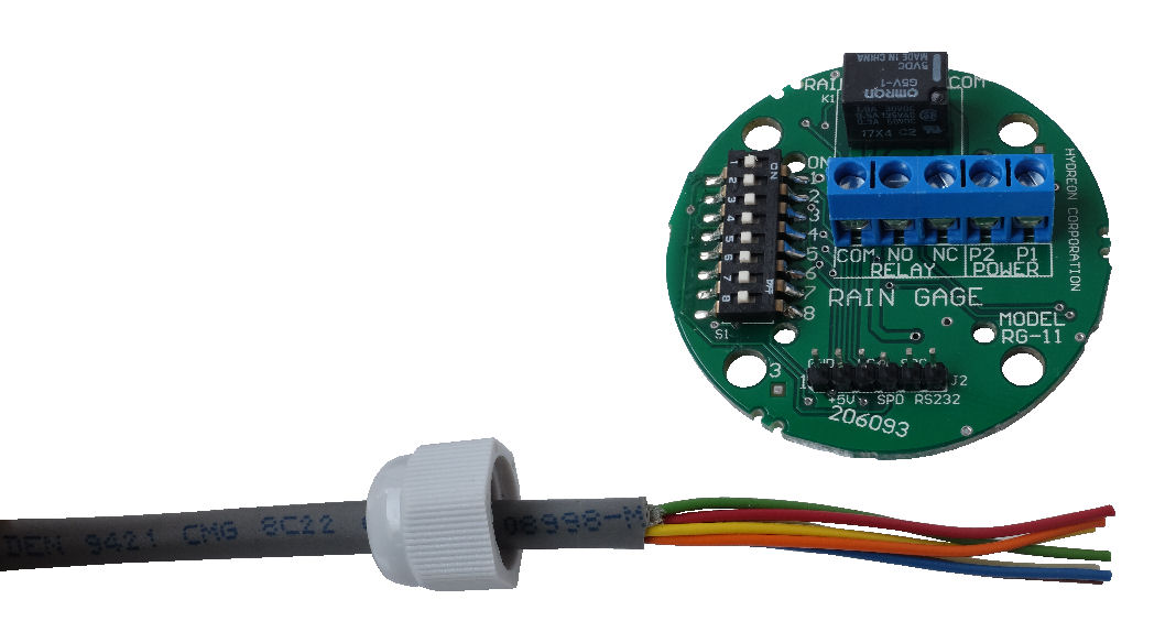
Strip the cable jacket 55mm
(diameter of the electronic circuit board).
The cable jacket diameter should be from about Ø4mm to Ø6mm, to ensure the cable gland can be screwed tight and have a good tight seal around the cable jacket for waterproofing.
We are using the multicore cable from Belden 9421 (8 core wires). The minimum number of wires required is 4 in order to operate the rain sensor. In this example, we are connecting up all the 5 screw terminal, so there will be 3 spare wire core.
Suitable Cable Part no.
 Belden 9421, 8 core 22AWG (Multi-strand 7x30AWG)
- Belden 4506, 7 core 22AWG Shield (Multi-strand 7x30AWG)
Cat5e network cable is a popular cable for non-network device connection. It has a reasonable cost and availability. Most Cat5e cable uses solid bare copper core conductor 24AWG. Single solid bare copper has a potential to break if there is frequent cable movement. For permanent installation where the cable is not easily accessible, it is ok to use a solid core cable. Otherwise, a multi-strand wire is recommended.
It is easier to strip the cable first before pulling it through the cable gland. This will expose the multi-core wires for the rain sensor board connection. Strip out about 55mm of the cable jacket from the cable end. The diameter of the PCB board is about 55mm. You can use it as a guide for stripping the cable to length.
Before inserting the cable to the cable gland, remember to put in the cable gland’s cap as illustrated in the photo. You will need to tighten this cap later to ensure a water-tight at this cable entry gland.
Inserting Cable
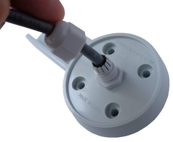
Next, we will need to insert the cable through the cable gland which is on the base of the rain sensor. A reminder to slip in the gland’s cap before you start inserting the cable.
Look out for the rubber gasket ring inside the cable gland, and insert the cable in slowly.
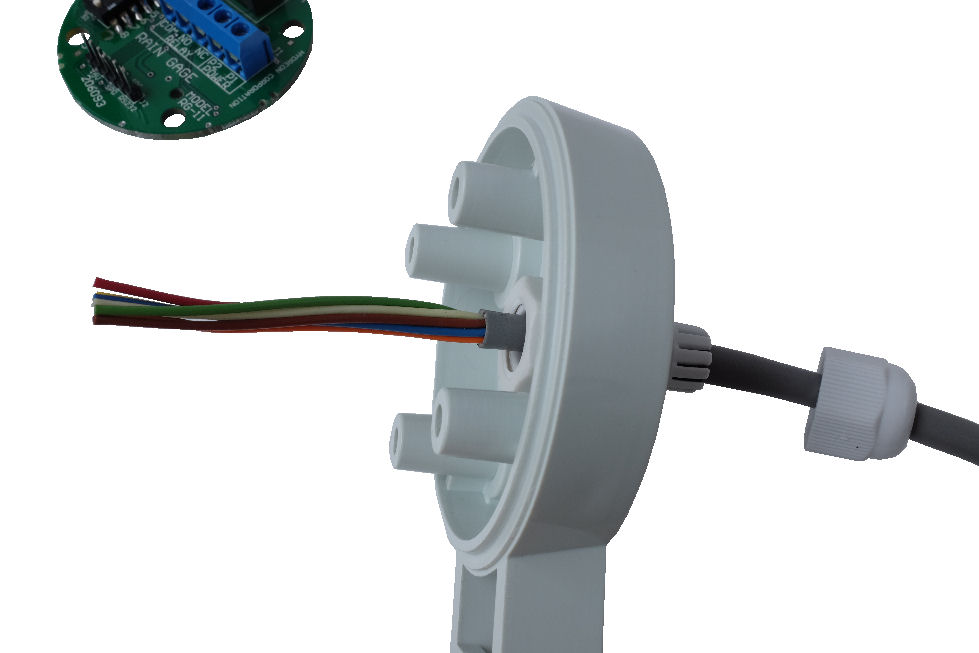
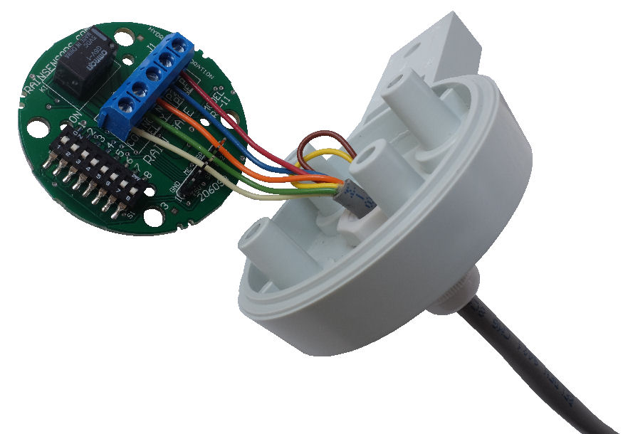
Continue to pull through the cable till the cable jacket is about 5mm through and out of the cable gland as illustrated in the photo.
When the cable is in the correct position, screw in the cable gland’s cap tight. This will ensure that the cable entry will be water tight, which waterproof the whole rain sensor electronic.
Connecting the Wires
Strip about 5mm off the end of the wire so that the copper strands are exposed. You can use the Ø5mm mounting hole on the circuit board as a guide for stripping the wire ends.
We need to strip the wire ends, which will then be screw tight onto the blue connectors.
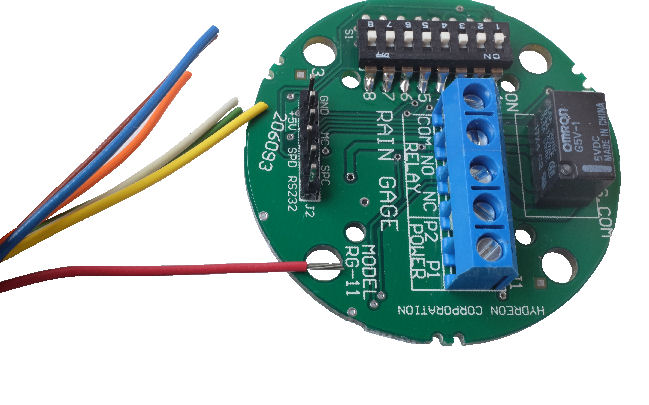
Connect the wires to the blue color connector. Take note of the wire color codes connected to the respective screw terminals (COM, NO, NC, P2, P1).
The number of wires required to be connected to the remotely installed outdoor rain sensor is about 3 to 5 cores. The minimum number of wires required is 3 if you connect a jumper from P1 (+ve Power Supply) to the COM terminal. This means the NO terminal will be enenergised if the rain sensor gets activated
For most situation, you will use 4 wires to use the dry contact available from the relay onboard the sensor.
If the implementation is not finalised yet or if you prefer a more flexible installation option, it is good to use a 5 wires cable to connect to the rain sensor.
The choice of wiring colour code is not strict. In practice, it is better to follow a standard, so that it is easier for future maintenance. The following table is a proposed wire colour code that you can follow.
| Pin No. | Connector Terminal | Propose Color |
| 1 | P1 (Power Input+) | ███ Red |
| 2 | P2 (Power Input-) | ███ Black or ███ Blue |
| 3 | NC (Normally Close contact) | ███ Orange |
| 4 | NO (Normally Open contact) | ███ Green |
| 5 | C (Common contact) |
███ White |
Configuring Rain Sensor Operating Mode
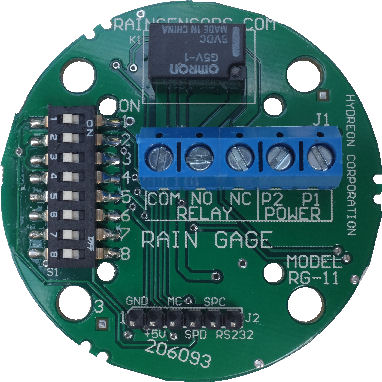
Before you assemble back the rain sensor optical dome cover, remember to configure the sensor mode of operation by setting the 8 way DIP switch (next to the blue colour connector), so that it behaves the right way for your rain sensing application.
You can configure the rain sensor for a variety mode of operations for different use case scenario. You can set up the rain sensor for the following operation.
Operation Modes
- Rain Sensor
- Tipping Bucket Rain Gauge
- Condensation Sensor
- Irrigation Control
- Water Drop Detector
Click here for more…
setting up the operation mode for rain sensor module.
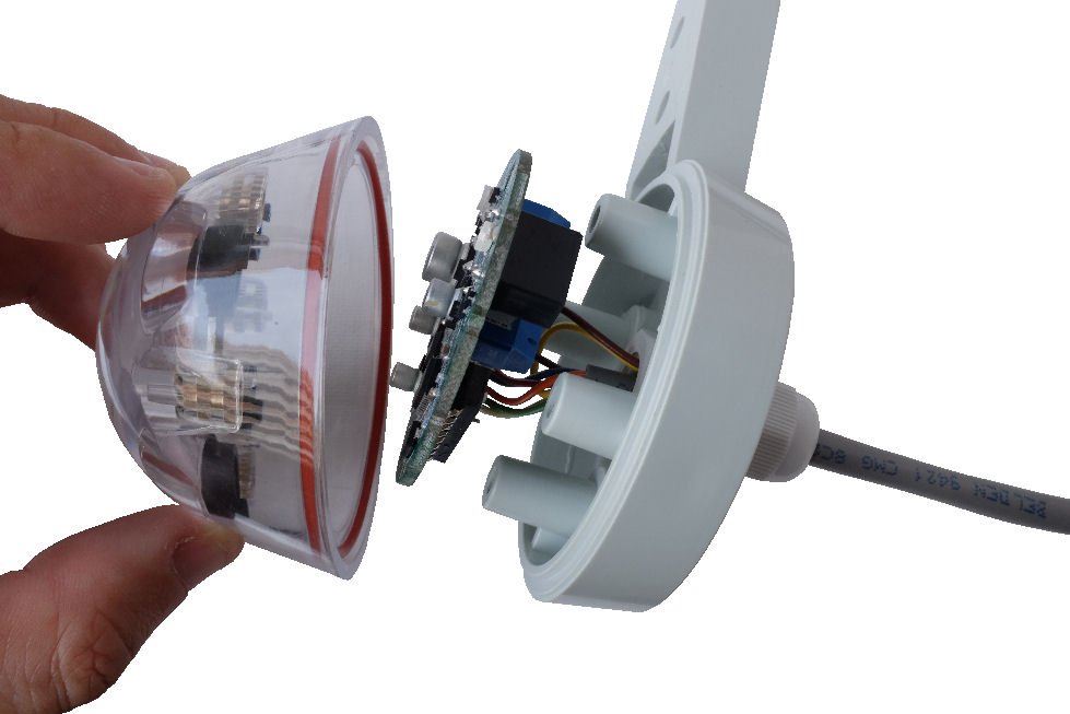
Assemble Back the Rain Sensor
Assemble the rain sensor casing, and secure it with the 4 screws from the bottom of the casing.
Rain Sensor Mounting
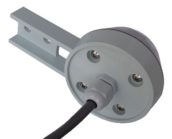
The rain sensor is now fully assembled with the cable wiring & secured with the 4 screws. The sensor is waterproof and has to be mounted outdoor to detect the rain.
A flat bar structure is recommended to mount the rain sensor with 2x M6 screw. Check out the rain sensor size & dimension page for more information to design your mechanical mount for the sensor.
Connecting Rain Sensor to Controller
The rain sensor has a total of 5 wire connection, for the input power and the relay output. The blue connector terminals are labeled on the circuit board for your installation.
Power
The input power to the rain sensor is the terminal P1 and P2. The rain sensor can accept a wide voltage range of 12V to 24V. The input voltage can be AC or DC voltage, the rain sensor can accept both type of power. There is no +/- polarity on the P1 and P2 terminal; you can just connect the pair of power line to either terminal. If you want to standardise the connection, you can let P1 be the +positive terminal while P2 is the -negative terminal.
Relay Output
The relay dry-contact output has 3 wire connection which is NC, NO, COM (Normally Close, Normally Open, Common Terminal). This relay will be be activated when rain is detected as an example. There are many scenario you can set to trigger the on board relay. It depends on the rain sensor operation mode that is configured.
The relay contact switch is rated for 24V 1A power. If you need a bigger rated relay contact switch, you can connect to an external relay which can handle the higher power capacity.
Integrate to Other Systems
Click here for more connection examples to integrate this rain sensor with other electronic controller and systems.
RG-11 Rain Sensor User Manual (PDF)
For more detail, you can also download this rain sensor user manual (*.pdf, file size 580KB) for reference.